View the thread, titled "Hi can someone clarify this?" which is posted in The Welcome Wagon :) on UK Plumbers Forums.

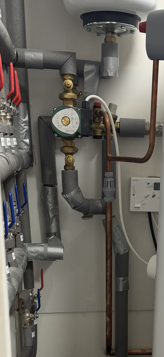
I have recently started a new job as a Facilities Manager, and one of the plumbing contractors said that he noticed an issue while he was working on a cylinder in a flat “the expansion vessel is being fed by the cold-water pipework, which includes a non-return valve between it and the cylinder, and that the non-return valve between the expansion vessel and the cylinder will render the expansion vessel ineffective, as it obstructs the necessary flow for pressure regulation?” I have contacted the original installer but there taking there time getting back can someone please clarify if this is the case from the pictures, if so it would be greatly appreciated. Thanks Ste
bb39590c-0478-4d74-83f5-229b3b6ccb18.jpeg
748a2806-f67a-4988-9f19-3f830b45500d.jpeg
IMG_9676.png
 
My reading of the photos is that the vertical port on the combination valve (balanced cold water outlet) should go to the cold water distribution manifold. The horizontal outlet port should go to the expansion vessel then across a swept-tee where the secondary-return joins and finally to the cylinder cold water inlet.

In short, I agree with your contractor. I'd also expect to see a check valve (to prevent back flow) between the secondary-return pump and the swept-tee but I can't see this on the photos.

You need a plumber who has been certified to work on unvented hot-water systems ('G3 qualified') to compare the installation with the MI's and rectify any errors.
 
Looking at the set up I’m wondering is this installation in a small plant room?

If it is then the expansion vessel is installed correctly. It’s a white expansion vessel which indicates it’s for fresh water only and should be at 3 bar. The valve below the expansion vessel is a shielded gate valve to isolate the expansion vessel from the system for maintenance to the vessel.

I am a G3 plumber but checking out a system from a photo isn’t ideal. Get a G3 plumber in to give it the once over but to me, from the photos it looks good.

Hope this helps.
 
Thank you all for your replies, your help is much appreciated, the cylinder is in a flat, and it is on the cold supply, but after looking at the diagram below it looks like the expansion vessel should be on the cold supply going to the cylinder? Where as on the installation above it’s on the other side that is supplying the cold water to the individual rooms? Also the pipe feeding the cylinder is coming out of the underside of grey side of the valve rather than the bottom pipe of the other red side? If that makes any sense? I think that is what the contractor was trying to describe to me.
IMG_9677.png


My problem is both the installer and the contractor are both G3 Plumbers? I may need to ask a third G3 plumber to confirm as the original installers haven’t got back to me, and just to clarify there is a pressure relief valve on the cylinder itself, similar to the diagram below.
 
Thank you all for your replies, your help is much appreciated, the cylinder is in a flat, and it is on the cold supply, but after looking at the diagram below it looks like the expansion vessel should be on the cold supply going to the cylinder? Where as on the installation above it’s on the other side that is supplying the cold water to the individual rooms? Also the pipe feeding the cylinder is coming out of the underside of grey side of the valve rather than the bottom pipe of the other red side? If that makes any sense? I think that is what the contractor was trying to describe to me.
View attachment 95450


My problem is both the installer and the contractor are both G3 Plumbers? I may need to ask a third G3 plumber to confirm as the original installers haven’t got back to me, and just to clarify there is a pressure relief valve on the cylinder itself, similar to the diagram below.

The second one is correct, first doesn’t know what he’s doing unless it’s an internal air gap cylinder, as it looks like a gledhill unvented cylinder second one is still correct
 
Thank you all for your replies, your help is much appreciated, the cylinder is in a flat, and it is on the cold supply, but after looking at the diagram below it looks like the expansion vessel should be on the cold supply going to the cylinder? Where as on the installation above it’s on the other side that is supplying the cold water to the individual rooms? Also the pipe feeding the cylinder is coming out of the underside of grey side of the valve rather than the bottom pipe of the other red side? If that makes any sense? I think that is what the contractor was trying to describe to me.
View attachment 95450


My problem is both the installer and the contractor are both G3 Plumbers? I may need to ask a third G3 plumber to confirm as the original installers haven’t got back to me, and just to clarify there is a pressure relief valve on the cylinder itself, similar to the diagram below.
Ok, I've re examined the photos and this is what I've come up with. I thought the pipe (connected to the expansion vessel) was feeding the cylinder in another room.

Lets concentrate on the combination valve.

The mains (at mains pressure) is entering the combi valve from the right (picture 3) which is correct.

It then goes through the pressure reducing part of the combi valve (the grey bit).

From the bottom of the grey bit is the balanced feed which goes to feed the cylinder (incorrect).

Then there's a double check valve (inside the combi valve).

The red bit is the PRV (Pressure Release Valve) part of the combi valve which is pipped correctly.

Then there is a tee which branch's up to a shielded (tamper proof) gate valve then into the expansion vessel (incorrect).

The pipe then carries on to feed whatever it feeds (taps etc.)

Now the correct way.

The balanced pipe (vertical one) should be feeding taps to sinks, basins etc. The outlet after the PRV (horizontal one) should be going to the cylinder.

The fix would be to rotate the combi valve 90 degrees so the balanced feed goes to the taps and the expansion feed goes to the cylinder.

It will take a bit of re-piping to get it correct.

Hope this helps.
 

Official Sponsors of Plumbers Talk

Reply to the thread, titled "Hi can someone clarify this?" which is posted in The Welcome Wagon :) on Electricians Forums.

Weekly or Monthly Email Digest

Back
Top